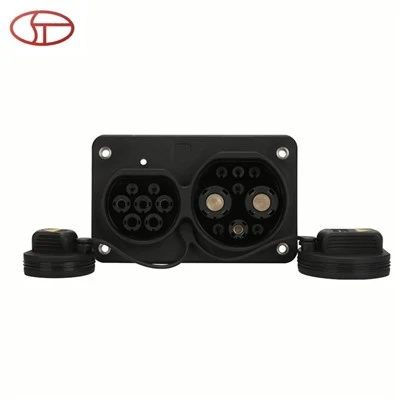
As a supplier of High Voltage Interlock (HVI) Connectors, ensuring the reliability and durability of our products is of utmost importance. One critical aspect of this is testing the vibration and shock resistance of these connectors. In this blog post, I’ll share our insights and methods on how to effectively test the vibration and shock resistance of HVI connectors. High Voltage Interlock Connector
Understanding the Importance of Vibration and Shock Resistance Testing
HVI connectors are widely used in high – voltage electrical systems, such as electric vehicles, renewable energy storage systems, and industrial power distribution. These environments are often subject to various levels of vibration and shock. For example, in an electric vehicle, the connectors are exposed to vibrations from the engine (if there is a range – extender engine), road bumps, and the movement of the vehicle itself. In industrial settings, machinery operation can generate significant shocks and vibrations.
If an HVI connector fails due to vibration or shock, it can lead to serious consequences. Electrical arcing may occur, which can damage the connector and other components in the system, and in the worst – case scenario, it can cause a fire or electrical hazard. Therefore, thorough testing of vibration and shock resistance is essential to ensure the safety and reliability of the entire high – voltage system.
Pre – test Preparations
Before conducting the vibration and shock resistance tests, several preparations are necessary.
Component Inspection
First, we need to visually inspect the HVI connectors. Check for any visible defects such as cracks, loose parts, or improper assembly. We also measure the basic electrical parameters of the connectors, including contact resistance, insulation resistance, and dielectric strength. These initial measurements serve as a baseline for comparison after the tests.
Test Setup
We use specialized test equipment for vibration and shock testing. For vibration testing, a vibration table is used. The vibration table can simulate different vibration frequencies, amplitudes, and waveforms. We need to secure the HVI connector firmly on the vibration table to ensure that the vibrations are accurately transmitted to the connector.
For shock testing, a shock tester is employed. The shock tester can generate sudden and intense impacts with different acceleration levels and durations. Similar to the vibration test, the connector must be properly fixed on the shock tester to ensure reliable test results.
Vibration Testing Procedures
Frequency and Amplitude Selection
The selection of vibration frequency and amplitude is based on the expected operating conditions of the HVI connector. In general, we test the connectors at a range of frequencies from 10 Hz to 2000 Hz, which covers most of the vibration frequencies encountered in real – world applications.
The amplitude of the vibration is also carefully determined. For example, in automotive applications, the amplitude may be set according to the industry standards, such as ISO 16750 – 3, which specifies the vibration requirements for automotive electrical components.
Test Duration
The test duration is another important factor. We typically conduct vibration tests for a minimum of 24 hours. During this time, the connector is continuously subjected to the specified vibration. This long – term testing helps to simulate the cumulative effect of vibrations over the product’s lifespan.
Monitoring During the Test
Throughout the vibration test, we continuously monitor the electrical parameters of the HVI connector. We use data acquisition systems to record the contact resistance, insulation resistance, and any changes in the electrical signals. Any significant changes in these parameters may indicate potential problems with the connector’s performance under vibration.
Shock Testing Procedures
Shock Profile Definition
Shock testing involves subjecting the HVI connector to sudden impacts. The shock profile is defined by parameters such as acceleration, duration, and pulse shape. For example, in some industrial applications, a half – sine shock pulse with an acceleration of 50 g and a duration of 11 ms may be used.
Multiple Shock Cycles
We usually perform multiple shock cycles on the connector. Each shock cycle represents a single impact. By conducting multiple shock cycles, we can simulate the repeated shocks that the connector may experience in its actual use.
Post – shock Inspection
After the shock test, we conduct a detailed inspection of the connector. This includes visual inspection for any physical damage, such as broken pins or cracked housings. We also re – measure the electrical parameters to check if the shock has affected the connector’s performance.
Data Analysis and Evaluation
Once the vibration and shock tests are completed, we analyze the data collected during the tests.
Electrical Parameter Changes
We compare the electrical parameters measured before and after the tests. A significant increase in contact resistance may indicate that the vibration or shock has caused poor contact between the connector pins. A decrease in insulation resistance may suggest damage to the insulation material.
Physical Damage Assessment
We assess the physical damage to the connector. If there are visible cracks or broken parts, it is clear that the connector has failed to withstand the vibration or shock. However, even if there is no visible damage, the electrical parameter changes can still indicate potential problems.
Based on the data analysis, we evaluate whether the HVI connector meets the required standards for vibration and shock resistance. If the connector passes the tests, it can be considered suitable for use in high – voltage systems. If it fails, we need to identify the root cause of the failure and make improvements to the design or manufacturing process.
Quality Assurance and Continuous Improvement
As a supplier of HVI connectors, we have a strict quality assurance system in place. The vibration and shock resistance tests are an integral part of our quality control process. We use the test results to continuously improve our products.
Design Optimization
If the test results show that the connector has weaknesses in vibration or shock resistance, we may optimize the design. For example, we can improve the mechanical structure of the connector to enhance its ability to withstand vibrations and shocks. This may involve changing the shape of the housing, increasing the thickness of the pins, or using more flexible materials.
Manufacturing Process Improvement
We also review our manufacturing process. Ensuring proper assembly and soldering of the connector components is crucial for its vibration and shock resistance. By improving the manufacturing process, we can reduce the occurrence of defects and improve the overall quality of the connectors.
Why Choose Our HVI Connectors
Our commitment to rigorous vibration and shock resistance testing sets our HVI connectors apart from the competition. We understand the critical role that these connectors play in high – voltage systems, and we are dedicated to providing products that are reliable and safe.

Our connectors have been tested to meet or exceed industry standards, ensuring that they can withstand the harsh conditions of real – world applications. Whether you are in the electric vehicle industry, renewable energy sector, or industrial power distribution, our HVI connectors can provide the performance and reliability you need.
Energy Storage Connector If you are looking for high – quality HVI connectors with excellent vibration and shock resistance, we invite you to contact us for a procurement discussion. Our team of experts is ready to assist you in finding the right connector solutions for your specific needs.
References
- ISO 16750 – 3: Road vehicles — Environmental conditions and testing for electrical and electronic equipment — Part 3: Mechanical loads
- SAE J1673: High Voltage Interlock Circuit Requirements for Hybrid Electric Vehicles
- IEC 60512 – 6 – 1: Electronic equipment connectors — Tests and measurements — Part 6 – 1: Vibration (sinusoidal) tests — Test 6a
Zhejiang Shitu Electric Co., Ltd.
As one of the most professional high voltage interlock connector manufacturers and suppliers in China, we offer a wide range of products with superior quality. Please feel free to buy custom made high voltage interlock connector from our factory. Good service and reasonable price are available.
Address: 1st and 2nd floors of Building C, Yueshang Entrepreneurship Park, Yueqing Economic Development Zone
E-mail: stdq@cnshitu.cn
WebSite: https://www.shitu-connect.com/